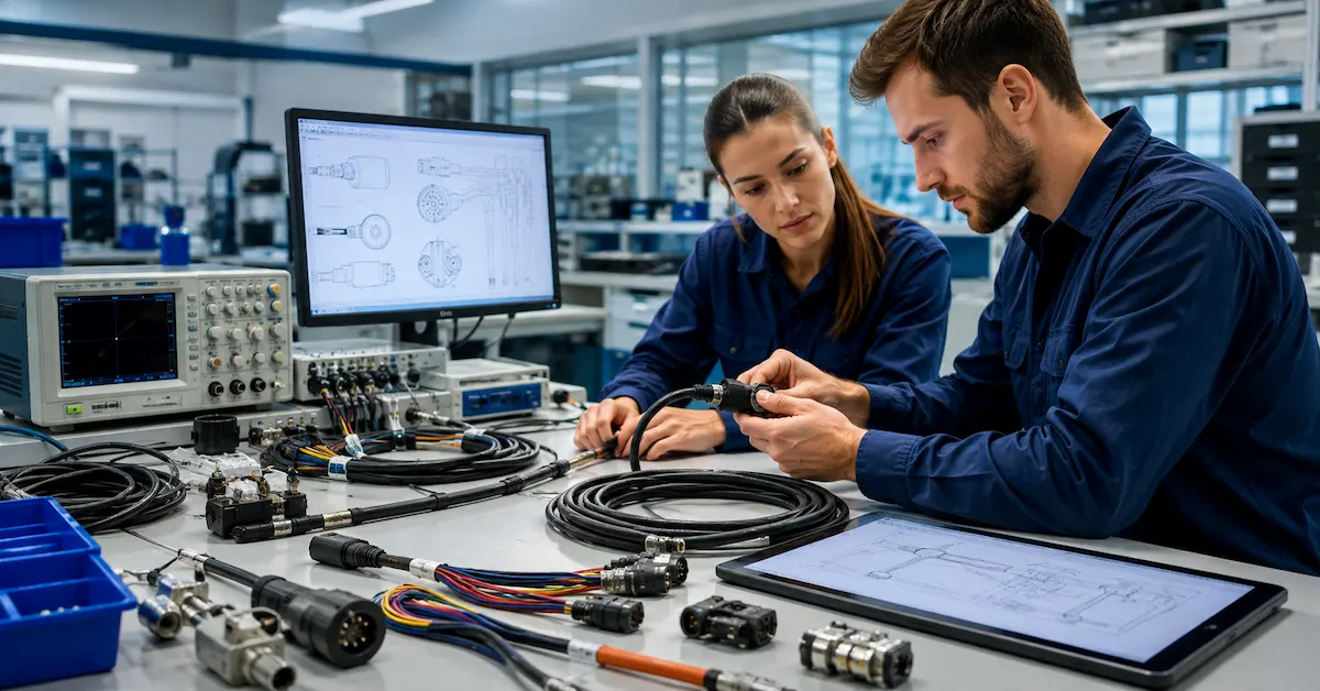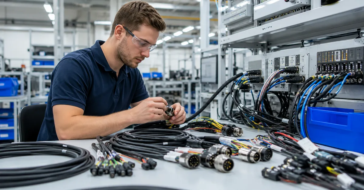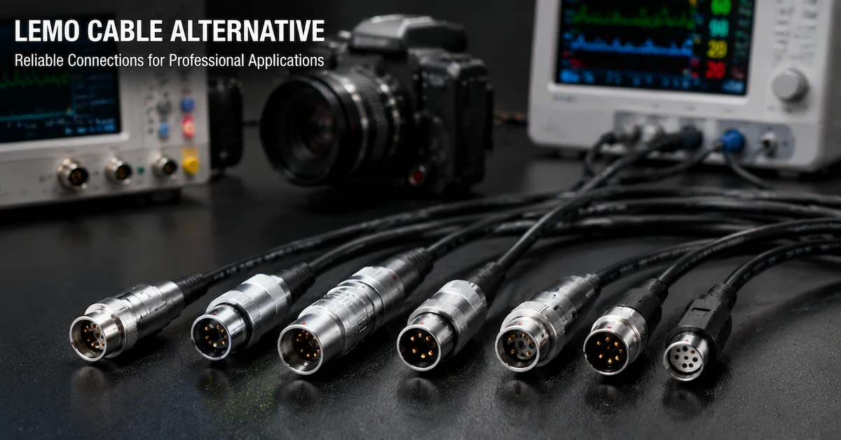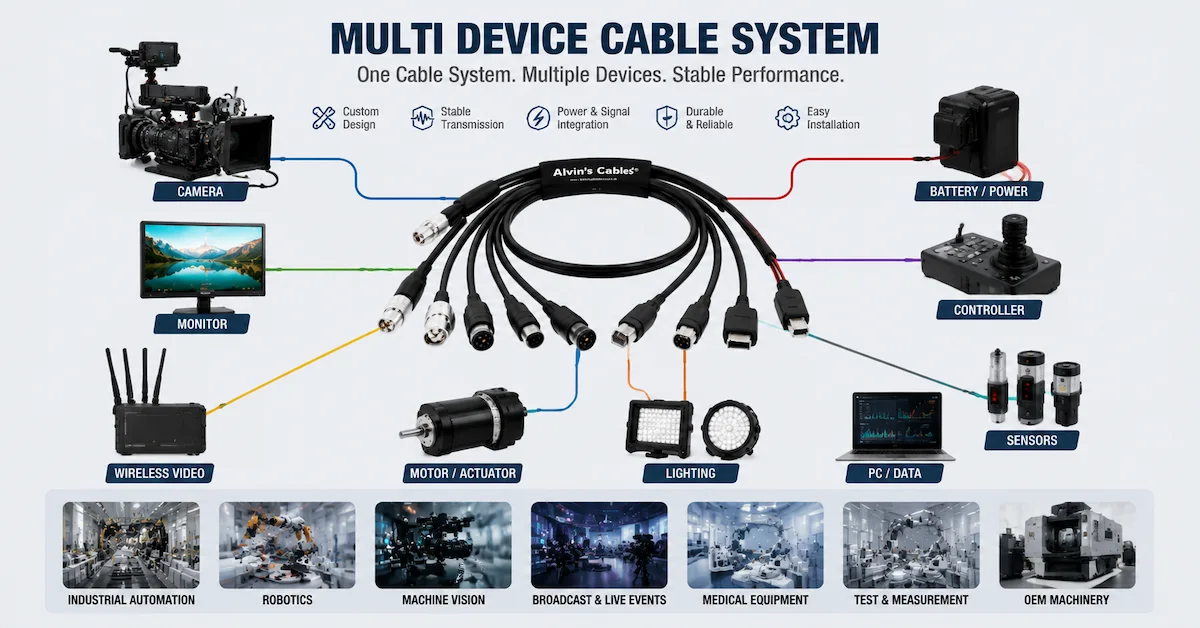
Reliable cable connection solutions help equipment manufacturers connect power supplies, sensors, cameras, controllers, monitors, communication modules, and other electronic components within one stable system.
For B2B buyers, a cable connection is not only a cable with two connectors. It must match the equipment interface, pinout, voltage, current, signal type, cable length, installation space, shielding requirement, movement conditions, and working environment.
A poorly planned connection may cause loose connectors, unstable signals, voltage drop, electromagnetic interference, difficult installation, or repeated cable failure. A properly designed cable assembly helps simplify equipment integration and supports stable long-term operation.
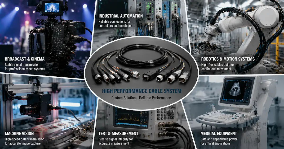
Alvin’s Cables supports custom cable assemblies and connector solutions for professional video equipment, industrial automation, machine vision, medical devices, test instruments, robotics, and OEM electronics.
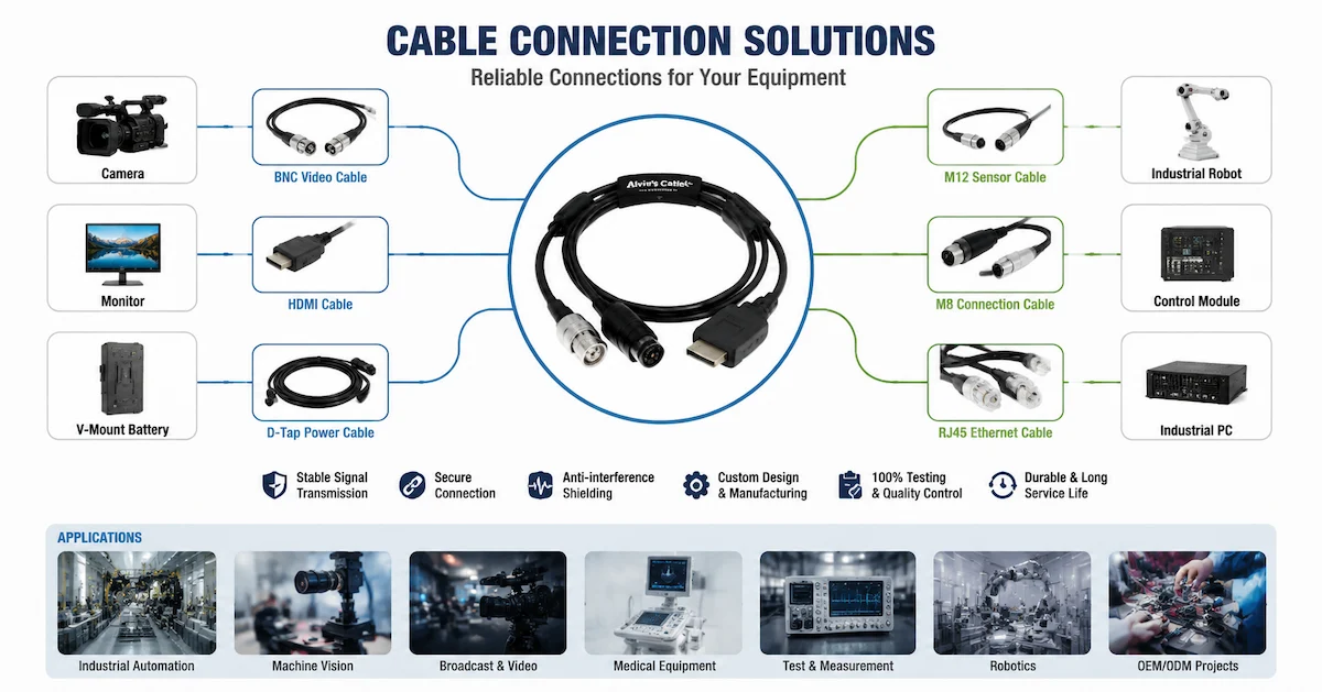
What Are Cable Connection Solutions?
Cable connection solutions are complete cable assemblies designed to connect two or more equipment interfaces while meeting specific electrical, mechanical, and environmental requirements.
A complete solution may include:
- Cable and conductor selection
- Connector identification
- Custom pinout
- Signal or power wiring
- Shielding and grounding
- Cable length and branch layout
- Straight or right-angle connectors
- Strain relief
- Overmolding
- Labels and packaging
- Electrical and functional testing
Unlike a standard off-the-shelf cable, a custom connection solution is developed around the actual equipment and application.
Where Are Cable Connection Solutions Used?
| Application | Connection Requirement | Main Buyer Concern |
|---|---|---|
| Industrial automation | Sensors, controllers, PLCs, and power modules | Reliability and interference resistance |
| Machine vision | Cameras, triggers, lighting, and computers | Stable high-speed signal transmission |
| Professional video | Cameras, monitors, recorders, and power systems | Signal stability and field durability |
| Medical equipment | Device modules, displays, and control units | Wiring accuracy and consistency |
| Test instruments | Measurement equipment and signal sources | Contact stability and low interference |
| Robotics | Motors, sensors, controllers, and moving modules | Flexibility and strain relief |
| OEM electronics | Internal and external equipment interfaces | Compatibility and repeat production |
| Outdoor equipment | Power, data, and control connections | Moisture and environmental protection |
Each application may use different cable materials, connector types, shielding structures, and testing methods.
Why Cable Connection Design Matters
1. Connector Compatibility
Connectors that look similar may differ in pin count, keying, shell size, locking method, contact type, and electrical rating.
Before production, buyers should confirm:
- Connector brand or compatible type
- Connector model
- Plug or receptacle
- Male or female contacts
- Pin count
- Straight or right-angle design
- Keying position
- Panel-mount or cable-end structure
- Required mating connector
Clear photographs can help identify a connector, but a model number, drawing, or physical sample provides more reliable confirmation.
2. Correct Pinout and Wiring
A cable may fit mechanically but still fail if the wiring is incorrect.
The supplier should receive:
- Pin-to-pin wiring diagram
- Signal names
- Positive and negative polarity
- Voltage and current
- Grounding information
- Shield termination method
- Unused pin requirements
An approved wiring diagram should be controlled throughout sample and repeat production.
3. Stable Signal Transmission
Signal cables may be affected by cable length, conductor structure, shielding, grounding, connector quality, and nearby interference sources.
Signal-sensitive applications may require:
- Twisted signal pairs
- Foil shielding
- Braided shielding
- Double shielding
- Controlled impedance
- Shield-to-shell termination
- Separate power and signal conductors
- Shorter cable routing
Machine vision, video, audio, sensor, data, and test equipment cables often need more careful signal design than basic power connections.
4. Reliable Power Delivery
Power connections must support the required voltage and current without excessive heat or voltage drop.
Buyers should confirm:
- Rated voltage
- Continuous current
- Peak current
- Wire gauge
- Connector current rating
- Cable length
- Polarity
- Operating temperature
A connector or conductor that is too small may work during a short test but become unstable during continuous operation.
5. Mechanical Protection
Cable assemblies are often damaged near connector ends, branch points, or frequently bent sections.
Mechanical protection may include:
- Molded strain relief
- Flexible connector boots
- Heat-shrink reinforcement
- Protective sleeving
- Right-angle connectors
- Cable clamps
- Overmolded branch points
- Abrasion-resistant jackets
The correct structure depends on whether the cable is fixed, moved occasionally, handled frequently, or installed in a robotic system.
Common Connector Options
| Connector Type | Typical Application | Main Advantage |
| M8 | Compact sensors and industrial modules | Small industrial interface |
| M12 | Sensors, power, Ethernet, and automation | Rugged locking connection |
| Hirose | Cameras and compact electronic equipment | Multi-pin precision interface |
| RJ45 | Ethernet and equipment communication | Standard network connection |
| BNC | Professional video and test equipment | Secure signal connection |
| D-TAP | Camera and broadcast power systems | Common professional power interface |
| XLR | Professional audio and AV equipment | Durable locking connection |
| Push-pull connector | Medical, camera, test, and industrial systems | Fast and secure mating |
| HDMI | Cameras, monitors, and AV equipment | Digital video connection |
| Open-end wiring | Internal equipment integration | Flexible wiring connection |
| Custom connector | Specialized OEM equipment | Exact equipment compatibility |
Buyers can review available cable and connector categories through the Alvin’s Cables Products page.
Standard Cable vs Custom Cable Connection Solutions
| Option | Advantages | Limitations | Best For |
| Standard cable | Fast availability and lower initial cost | Limited length, pinout, and connector options | Simple replacement |
| Modified standard cable | Faster than full custom development | Limited structural optimization | Minor equipment changes |
| Custom cable assembly | Matches equipment and wiring requirements | Requires technical confirmation | OEM and professional systems |
| Multi-connector solution | Connects several modules in one assembly | More complex wiring control | Integrated equipment |
| Overmolded cable solution | Stronger mechanical protection | Higher setup requirement | Rugged and repeat production |
For equipment manufacturers, a custom connection solution often reduces installation work and improves long-term product reliability.
Common Customization Options
| Custom Option | Purpose |
| Custom cable length | Fits equipment routing and reduces clutter |
| Custom connector combination | Connects different equipment interfaces |
| Custom pinout | Matches device wiring |
| Custom wire gauge | Supports required current |
| Shielded cable structure | Reduces EMI/RFI interference |
| Flexible jacket | Supports compact routing |
| High-flex construction | Supports repeated movement |
| Right-angle connector | Saves installation space |
| Overmolding | Improves strain relief |
| Multi-branch layout | Connects several modules |
| Labeling | Simplifies installation and maintenance |
| OEM packaging | Supports branded product delivery |
The supplier should confirm these options before prototype production.
Cable Connection Development Process
Step 1: Application Review
The buyer provides information about:
- Equipment type
- Devices being connected
- Connector interfaces
- Electrical requirements
- Signal type
- Working environment
- Expected quantity
Step 2: Technical Confirmation
The supplier reviews:
- Connector compatibility
- Pinout
- Cable structure
- Wire gauge
- Shielding
- Cable routing
- Connector orientation
- Strain relief
Missing information should be clarified before production.
Step 3: Prototype Production
The sample should confirm:
- Connector fit
- Wiring accuracy
- Cable length
- Routing
- Signal or power performance
- Flexibility
- Appearance
Step 4: Equipment Validation
The buyer tests the sample in the actual equipment.
Important checks include:
- Installation fit
- Stable operation
- Signal transmission
- Power delivery
- Cable movement
- Connector retention
- Long operating time
Step 5: Production Preparation
After approval, both sides confirm:
- Final drawing
- Bill of materials
- Revision number
- Testing requirements
- Labels
- Packaging
- Production quantity
This process helps maintain consistency across repeat orders.
How to Evaluate a Cable Connection Supplier
| Evaluation Point | What Buyers Should Check |
| Application understanding | Can the supplier understand the equipment and operating conditions? |
| Connector capability | Can it identify and integrate different connectors? |
| Wiring support | Can it follow custom pinouts and diagrams? |
| Electrical knowledge | Can it evaluate signal, voltage, current, and shielding? |
| Mechanical design | Can it support routing, strain relief, and overmolding? |
| Prototype support | Can it produce samples before mass production? |
| Testing capability | Can it test continuity, short circuit, polarity, and function? |
| Production consistency | Can it reproduce the approved design? |
| Change control | Can it manage drawing revisions? |
| OEM support | Can it provide labels and packaging? |
A supplier should be evaluated on the complete development and production process, not only the quoted unit price.
Common Buyer Mistakes
Selecting Connectors by Appearance
Similar-looking connectors may not be interchangeable. Confirm the exact model, pin count, keying, and mating interface.
Providing Incomplete Wiring Information
A connector model alone does not explain how the cable should be wired. Provide a pinout or wiring diagram.
Ignoring Cable Routing
A technically correct cable may still be difficult to install if it is too long, too stiff, or uses the wrong connector direction.
Skipping Shielding Evaluation
Signal cables installed near motors, power supplies, lighting, or industrial equipment may require shielding and proper grounding.
Approving a Sample Without Equipment Testing
Test the cable with the actual equipment before approving repeat production.
Failing to Control Revisions
Drawings, labels, cable lengths, and pinouts may change during development. Every approved change should receive a new revision number.
Information Required for a Quote
To receive an accurate quotation for cable connection solutions, prepare:
- Equipment application
- Connector models or clear photographs
- Pinout or wiring diagram
- Cable and branch lengths
- Voltage and current
- Signal or data requirements
- Shielding and grounding requirements
- Connector orientation
- Flexibility or movement requirements
- Operating environment
- Prototype and production quantities
- Labeling and packaging needs
- Drawing, specification, or physical sample
Complete information reduces development time and quotation uncertainty.
Why Choose Alvin’s Cables?
Alvin’s Cables supports custom cable assemblies and connector integration for industrial automation, professional video systems, machine vision, medical equipment, test instruments, robotics, and OEM electronics.
Available support can include:
- Drawing- and sample-based development
- Custom cable length and pinout
- Signal, power, video, audio, data, and control cables
- M8, M12, Hirose, RJ45, BNC, D-TAP, XLR, HDMI, push-pull, and open-end solutions
- Shielded and flexible cable structures
- Cable harness and multi-branch assemblies
- Strain relief and overmolding
- Prototype and sample production
- Low-to-mid-volume repeat manufacturing
- Electrical and functional testing
- OEM labeling and packaging
Buyers can learn more about the company through the About Us page and review manufacturing and service advantages through Why Choose Alvin’s Cables.
FAQ
1. What are cable connection solutions?
Cable connection solutions are complete cable assemblies designed to connect equipment interfaces while meeting electrical, mechanical, signal, environmental, and installation requirements.
2. Can different connector types be combined?
Yes. A custom cable can combine different connectors, open-end wiring, panel-mount interfaces, or multiple branches.
3. Can power and signal be included in one cable?
Yes, but conductor size, shielding, grounding, separation, heat, and interference must be evaluated carefully.
4. Why is pinout confirmation important?
The pinout defines how every conductor connects between interfaces. Incorrect wiring may cause signal failure, unstable operation, or equipment damage.
5. Can cable connection solutions be developed from samples?
Yes. Physical samples can be evaluated, but drawings, pinouts, and electrical information should also be provided whenever possible.
6. What tests should a custom connection cable receive?
Testing may include continuity, short circuit, polarity, pinout, connector fit, dimensions, functional performance, and visual inspection.
7. Can Alvin’s Cables make prototype cable assemblies?
Yes. Alvin’s Cables supports prototype and sample production before low-to-mid-volume and repeat manufacturing.
8. How can I request a custom cable quotation?
Submit your connector details, pinout, cable length, electrical requirements, quantities, and available drawings through the Contact Us page.
Conclusion
Reliable cable connection solutions help professional and industrial equipment maintain stable power, signal, data, video, and control connections.
Buyers should evaluate connector compatibility, wiring accuracy, electrical requirements, shielding, routing, strain relief, prototype validation, testing, and production consistency before approving a cable assembly.
For a custom cable connection solution, contact Alvin’s Cables and provide your equipment application, connector information, pinout, cable dimensions, working environment, and order quantity.